
In this article we will dive a little deeper into the folder structure for the transmittal of digital data from the design team to the contractor being developed by the CLSA Central Valley Chapter Construction Committee. In the last article we reviewed the top-level of this structure, which contained 5 folders. The first folder is the Corridors folder. As we mentioned in the last article, the Corridors folder contains drawing files and text files that define horizontal alignments and vertical profiles for route corridors. A route corridor could be for a road, a railroad, a canal, a pipeline or any other long linear site improvement. Files for individual corridors on the project sites are contained in sub-folders of this top-level folder.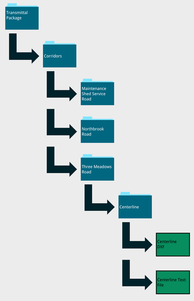
Let’s discuss in more detail how the Corridors folder would be set-up for an example transmittal. Within the Corridors folder are a set of sub-folders. There is one sub-folder for each route alignment in the projects. These folders are called a Route Folders. (For example: If the project as three (3) road alignments, there will be three (3) subfolders.) Within each Route Folder is another layer of sub-folders. There is one sub-folder for each major element of the route alignment. These folders are called Route Element Folders. (For example: For a simple two-lane paved road with no curb or sidewalk you would have three (3) sub-folders: centerline, right edge-of-pavement, and left edge-of-pavement.) Within each Route Element Folder there should be at least 2 files. The first is a DXF file that contains the route element geometry and a standard set of labels. The second is a simple ASCII text file that describes the route geometry and is easily read by both humans and computer software. Both of these files facilitate the transfer of route element data between computer programs. The third optional file is a PDF or image file that shows the route geometry.
The graphic shown with this article shows an example of the Corridors folder structure.
In our next article we will discuss the contents of the DXF file for the route element drawings. This will include describing the layer convention and the format for the drawings standard text labels.